The CIV 102 truss project gives an early example where I used prototyping of various candidate solutions to aid in evaluating the best one. It is also an illustration of a project where the client gives the engineer the initial problem followed by a set of DfX’s. Finally after making the optimal bridge we could design, we made sure it stayed true to the DfX’s initially given in the assignment description.
Overview of major points in project brief:
- Design a truss bridge made out of steel hollow structural sections (HSS)
- Span = 50m
- The bridge must have a “hanger” at the centre of its span as a support for its weight
- The bridge must NOT be statically indeterminate
- Other technical points about bridge height and width restrictions.
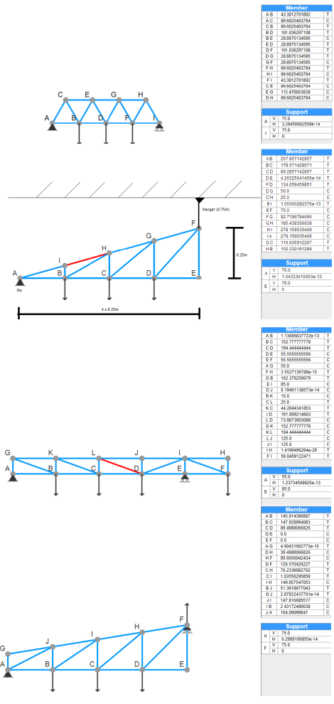
On reading through the project brief, my team decided that it would be a good idea to prototype several different truss bridge designs. Performing all the force-balance calculations for dozens of truss beams for several prototypes by hand would have been tedious. So, we used truss simulation software to speed up the process and gain some initial insight into the pros and cons of many truss configurations:
With the help of the simulation software, we could look at the forces to which various truss beams would be subjected. In terms of DfX (Design for X), my team wanted to focus on designing for manufacturability, cost, and aesthetics. Finally, after considering these DfX’s, we chose to proceed with the final prototype presented above.
Next, we had to do all the truss calculations by hand since the simulation did not model some of the specific circumstances required for this project. I.e. the simulation could only be used to model one half of the bridge as shown in the prototypes above. Another half of the bridge had to be modeled, and the way the two halves were joined in the middle had to be taken care of carefully to avoid making the bridge statically indeterminate.

Calculations for the load-bearing truss elements, and for wind bracing
After making the calculations, we made a final check to see if the costs were reasonably low. We were satisfied with the product’s adherence to DfX’s. Finally, we had a truss bridge:


